Project Eagle Eye - Precision Altitude Sensing for Defence Aircraft
I recently funded a project. Several technical details have been hidden due to the technology’s defence applications.
Background
The modern battlefield is a GPS denied environment. Ukraine is a example of this, where Russian’s GPS jamming devices are active. This means that any flying vehicle such as aircraft, missiles, or drones need alternatives for navigation.
I, together with some folks, experimented with such a navigation system.
Note: Several past approaches have been tried to solve this problem, and the following blog by Palantir does a good job of explaining all this → https://blog.palantir.com/the-future-of-drone-navigation-7236075fdedf
Let jump into the method we came up with.
Our idea was as follows →
- We would have an Camera (onboard the aircraft) that constantly clicks images of the ground, clicking several images per second.
- An onboard computer analyses the images for pixel transaction i.e. how much the pixels have shifted and in which direction, across two consecutive images.
- Then, we would translate the pixels movement into actual ground distance. If you do a bit of trigonometry, you will realise that we need the the aircraft altitude to perform this calculation.
- In order to get altitude, it was suggested that we active systems such as LiDAR or Radar. But then we run into stealth problems for the aircraft.
- As such we came up with a new method for gauging altitude using purely passive methods.
Fully Passive Altitude Sensing
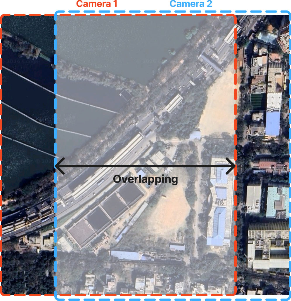
On the aircraft, we would have two camera’s onboard, that are fixed a set distance apart. Both the camera’s would simultaneously click two images of the ground directly below. Since the camera’s are apart, the two images of the ground below will be slightly different, but will also have overlapping sections as shown below -
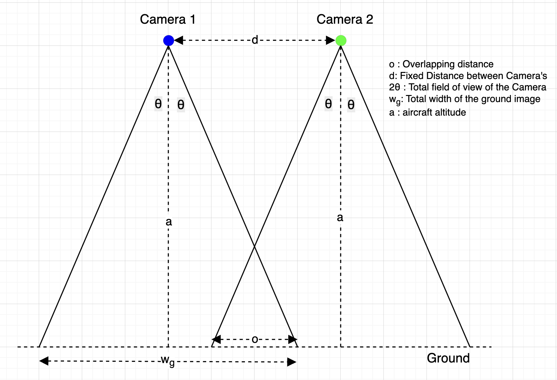
Then, we can do a bit of trigonometry to figure out that, if we know the distance between the two onboard cameras (d), and how much is the % overlap b/w the two images (k), then we can figure out the distance between the ground & the cameras (altitude a). Simplified math shown below -
Then we applied this concept in practice.
Attempt 1:
I tested out this approach myself at my apartment, and used by mobile camera to take the pictures of a door knob. The door acted as the point on the ground whose distance we need to determine. During the test, I translated the phone a set distance (20 cm), very carefully by hand, to serve the purpose of 2 camera’s by using just one phone.
I got an error of 30% for a distance of 4 meters.
Even if I were to use two different cameras that are fixed, there are going to be several sources of error, as following -
- It will be impossible to place the camera’s exactly parallel to each other, there is always going to be some non-zero angle. To get accurate answers, we would need to know this angle precisely, since the math showed us that the error was very sensitive to this angle, especially at typical flyings altitudes. Hence, we would need to develop a system to measures angles with high precision.
- There are not just one angle, but 3 for each camera - pitch, roll, and yaw.
- The same problem extends to the distance b/w the camera’s (d) too, and this becomes an increasingly bigger problem as the ratio of altitude to distance b/w camera’s increases.
- The camera’s would not be actually placed at the exact point they are supposed to be placed at.
- The reported Camera’s specifications such as focal length etc would also have some error, as given by the Camera manufacturer.
- Furthermore, in real world deployment, the aircraft would go thru wear and tear, vibrations, and shocks, which could change the angles and distances slightly over time.
I would like to repeat that that Math showed us that the the total error was quite sensitive to the above sources of errors, and we would need high precision to keep total error within limits. Tracking all sources of errors, and taking measurements that precisely seemed overkill, and to be honest impractical.
At this point, I documented the problem statement, and put out an ad inviting people to solve this problem. Within a day, an ex-NASA engineer reached out, and on the first call itself, it was clear he was going to be better at solving this problem than me. So we started working together.
Attempt 2:
Calibration
We realised that the error tracking problem we faced in Attempt 1 was actually very common in hardware engineering, and the way to get around it was something known to all hardware engineers - calibration. This involves carrying out a couple of experiments (in which the distance to be measured is known beforehand), and using the data to back-calculate the inaccuracies in the setup, and distill them in a couple of constants. Since the inaccuracies are fixed across experiments, we can use them for further experiments.
As long as the Camera setup is not disturbed across experiments, our calibration constants are valid, and can be re-used.
This means we don’t have to track all errors from ground up.
Change in Setup Geometry
We made another change over Attempt 1. We learnt that the fixed distance b/w the onboard cameras (d) would need to be several meters to ensure that our device has sufficient accuracy at typical flying altitudes. This would create limitations around installations on the aircraft, especially drones.
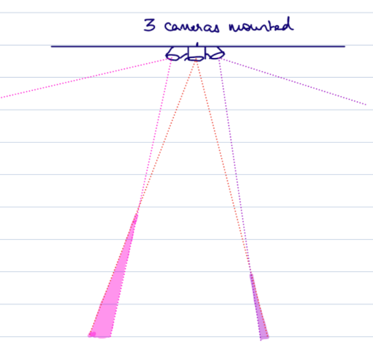
We went ahead with an alternative setup where camera’s were mounted close to each other, but at an angle, as shown below. The angle b/w cameras serves the same function as the fixed distance separation i.e. creating slightly different but overlapping images. Also, 3 cameras were used to increase accuracy. The maths changes a bit, but the basic principle stays the same.
Note that, the amount of overlap is a function of the altitude and angles b/w cameras. Hence, different angles b/w camera’s would be suited for different altitude regimes.
Switch to Professional Camera for more control
We also made a switch from Phone camera to a professional camera with an aspherical lens. We learnt that the phone camera lens distorts images in ways we cannot control, nor predict. Aspherical lenses fix that. Futhermore, phone cameras make a large number of software level edits which are not open source.
This also meant that we had a clear understanding of the geometry of how light was going through the lens and forming the image. This made it possible to build math models without any un-validatable assumptions.
Experimental Setup
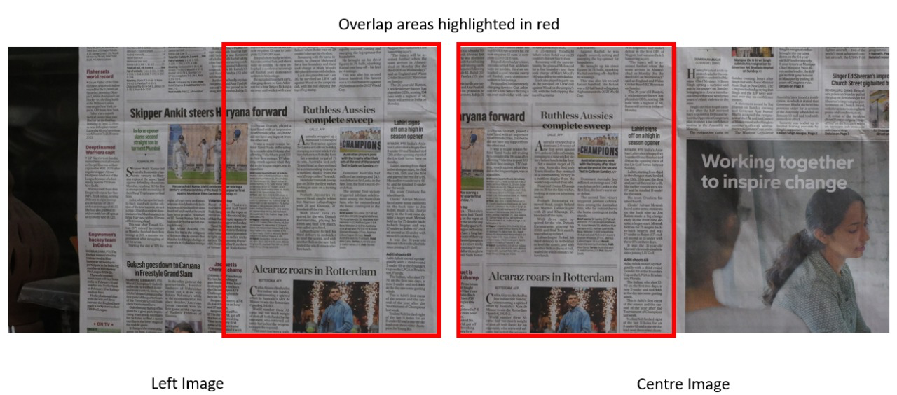
For the test, we mounted a single Camera on a swivel mechanism that allows the camera to be rotated very accurately. So we needed just one Camera instead of 3. We took images of a newspaper screen in front on the camera, as shown below. (a Bosch GLM40 laser was used to determine the actual distance of the newspaper screen, for both calibration experiments, and final test).
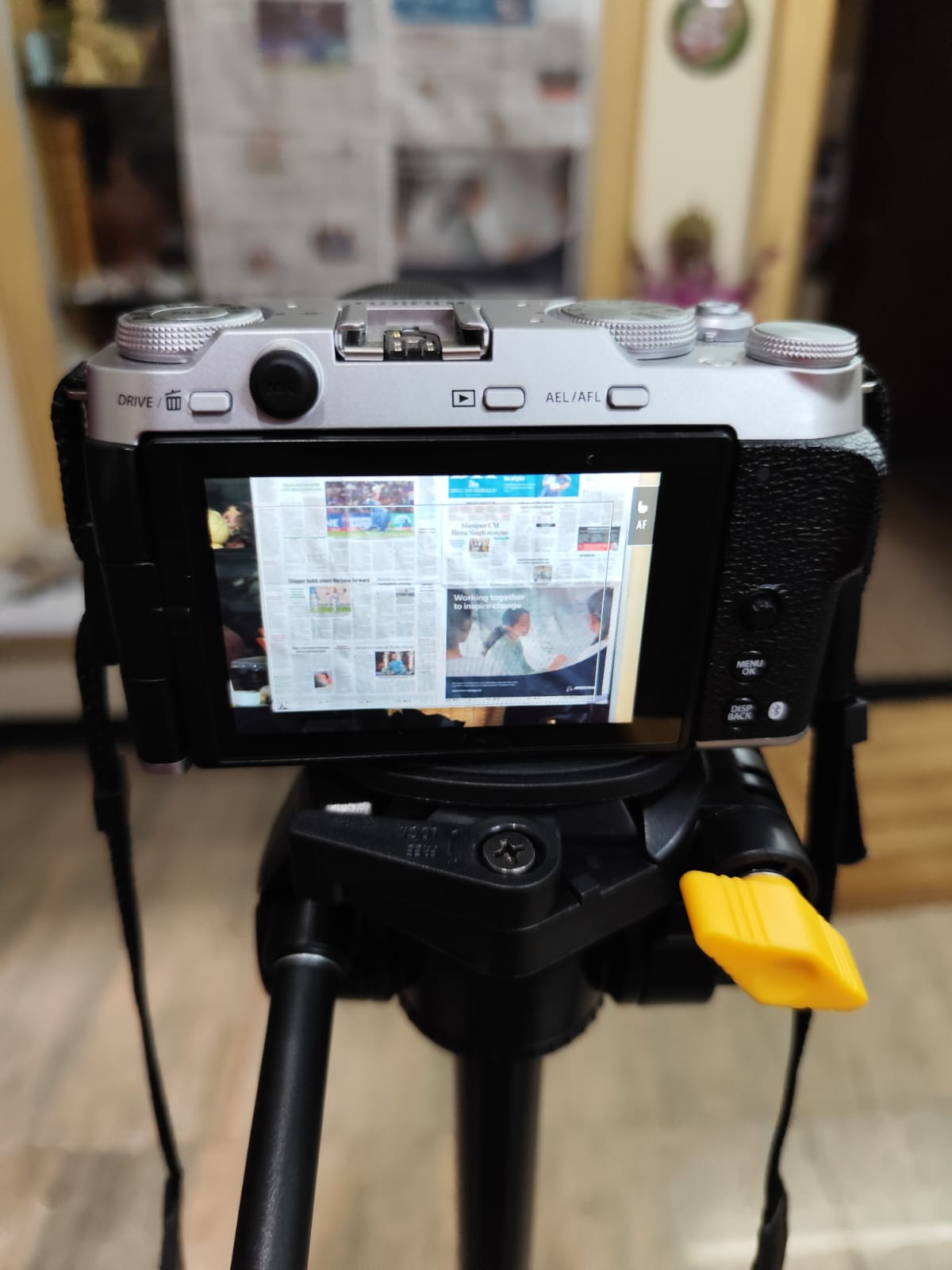
We took 2 images of the screen, one in left position, and one in centre position of the Camera.
Final data and Results
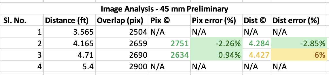
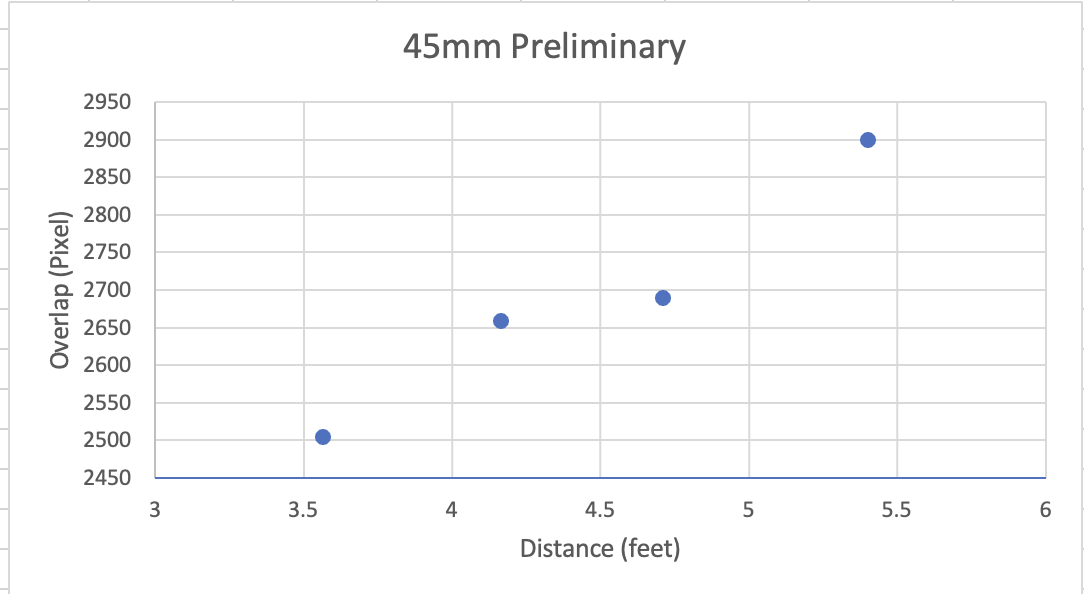
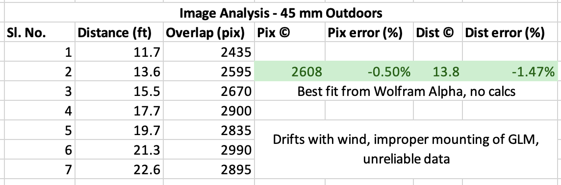
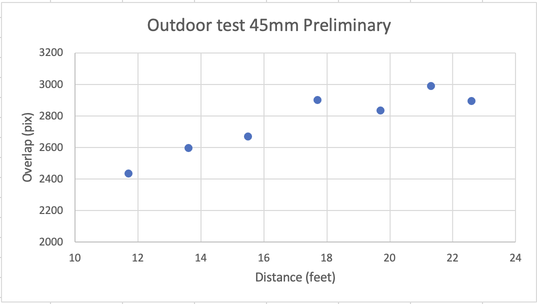
We have compiled the results in the tables and charts below. We achieved an error rate of 2.85% and 6% for distance measurements in the 3 to 6 feet range, with the error rate improving to 1.47% for the distance in 10-17 feet range.
Next Steps -
We got good encouraging results, and in future, we shall test our approach on longer distances.
In case you are interested in this project for some reason, please do reach out, we will be happy to collaborate.
<share on the semiconductor RnD group chat>
Appendix
Before trying our main method, which is the topic of this article, we also tried some methods that failed, and they are below.
Method 1: Using off the shelf “inertial sensors” for Inertial Navigation
This uses a combination of inertial sensors such as accelerometer and gyroscope, which measure the instantaneous linear and angular acceleration of the object. Then we can numericallly integration this data to arrive at linear & angular velocity and displacement.
We carried out some tests by collecting data using phone sensors, and then performed numerical integration on the same.
- We found the Gryo data to be generally accurate, and we were able to acurately arrive at the angualr position of the phone
- However, the accelerator data was super noisy and inaacuate, and could not get correct results for displacement.
We later learnt that this is a tried and tested method, and does not really work for long distance navigation due to “drift” build up. I kindly leave it for the reader to google this. So we moved on to second approach.
Method 2: VizNav - Visual Navigation
Comparison wtih onboard satellite imagery.
The idea was the the aircraft would have a pre-downloaded database of satellite images of the ground along the planned flight trjectory. Then, the onboard sensors would keep clicking the
- Featureless environments such as deserts, oceans
- Condtanyl chaing features such as forests. Satellite images are not updated frequency.
- Limitations around altiatures when flying over cities
- Availablelity of latest satellite imagery
- Satellite images are clicked from vertain altiatude, which aricraft altivtides are lower, thereby making image compairson harder, since images clicked from aircraft would look diffferent.
Note:
<this can be used as a passive radar system or guidance system for missiles in air defence systems>